
Advantages of contactless transmission technology
Inductive transmission systems are used in many applications in our daily lives to increase the convenience and safety of electrical devices. As a practical example, we all know the electric toothbrush or the electric shaver. These devices are used in an environment where contact-based electrical connections reach their limits. In environments with moisture, cleaning agents and other substances, energy transmission via mechanical contacts is unfavorable and such systems cannot be expected to have a long service life. With contactless designs, encapsulated devices can be created that function reliably in critical environmental conditions over the long term. They also offer increased protection for the operator against all hazards that naturally emanate from electrically operated devices.
Applications with inductive energy transfer systems
Inductive energy transmission systems offer decisive advantages in various applications. The following examples show the broad applicability of this technology in various product areas:
In industrial robots, inductive transmission systems enable a continuous supply of energy and data to robot arms in production facilities without mechanical restrictions.
Medical devices such as pacemakers or insulin pumps benefit from contactless energy transmission by supplying these systems with electrical energy without invasive interventions.
Rotating camera systems or surveillance cameras can function uninterruptedly with inductive energy transmission systems as they are continuously supplied with energy. A direct cable connection is not required.
In modern vehicles, rotating components such as steering wheels or sensors are supplied with energy and data by inductive transmission systems.
In wind turbines, the rotors can be supplied with reliable and maintenance-friendly control information using inductive systems.
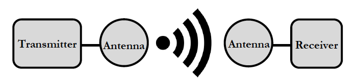
- Bild 1 – Basic structure of an inductive energy transfer system

Wireless transmission system with pot core coils
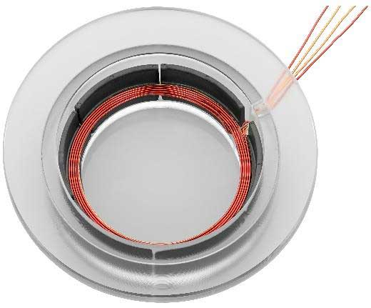
A stationary energy transmission system can be constructed, for example, with two pot core coils. In this system, the coupled ferrite pair consists of NEOSID pot cores Sch14. The transmitter and receiver coils are shown in the figures below:
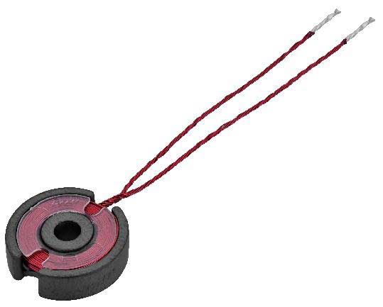
- Picture 2 - Primary/transmitting coil

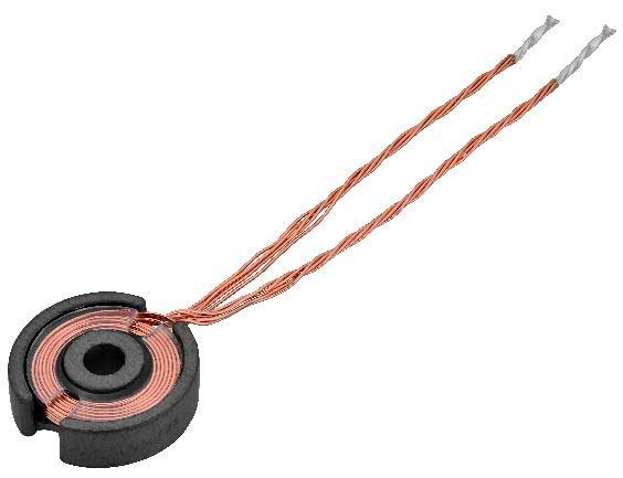
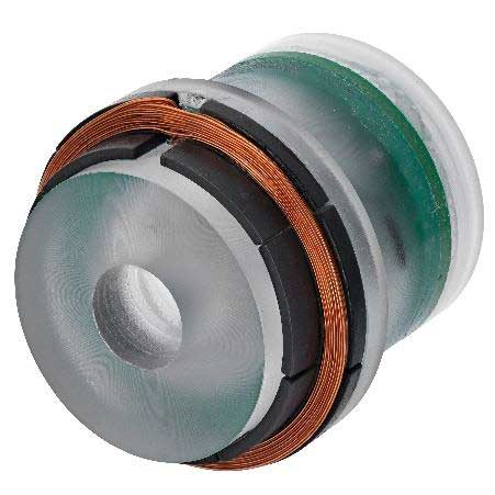
- Picture 3 - Secondary/receiver coil

The transmitting and receiving coils are mechanically and electrically separated from each other, e.g. by encapsulating them separately in housings. The separation of the two coils creates an air gap between the two ferrite cores. The air gap leads to a reduction of the coupling factor in the transmission system and increases the magnetic leakage field and thus the leakage inductance. In this Sch14 ferrite system, the maximum air gap is around 2.6 mm. Above this value, the two coils no longer couple with each other or the magnetic field of the transmitter coil runs outside the receiver coil and no more energy can be transmitted.
The encapsulation of the receiver coil is shown as an example in the following figure:
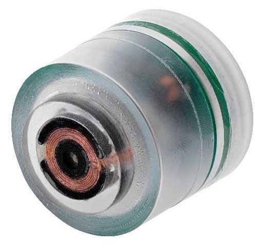
- Picture 4 - Secondary/receiver coil in the housing

For demonstration purposes, we have set up a system consisting of a transmitting and receiving coil. The transmitting coil is installed in a housing. An electronic circuit generates an alternating voltage which is applied to the transmitting coil to transfer energy.

- Picture 5 - Stationary energy transmission system consisting of transmitter and receiver coil in the housing

The maximum transmittable power in such a transmission system depends on the maximum permissible current density. The diagram below shows the measured temperature behavior of a winding in the Sch14 ferrite system at an operating frequency of f=100kHz. This diagram can be used to determine the maximum current density for a desired operating temperature.
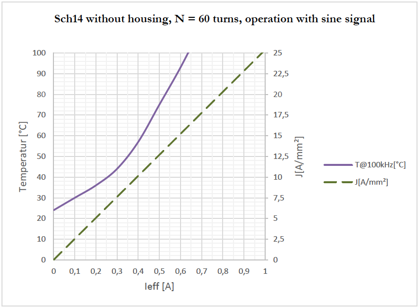
- Figure 6 - Temperature behavior and operating current

It is interesting to know the maximum power that can be transmitted by the system depending on the air gap between the coils. This is shown as an example for this transmission system at an operating frequency of 100kHz and a maximum coil temperature of T=60°C:
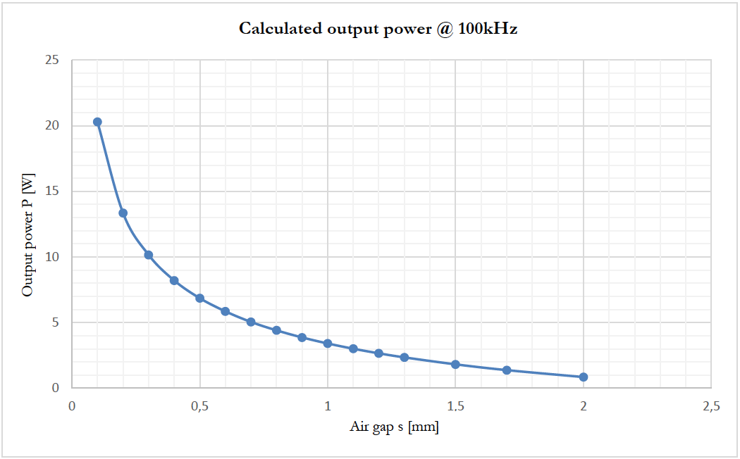
- Picture 7 - Output power with different air gaps

Rotating energy transfer system with special designed cores
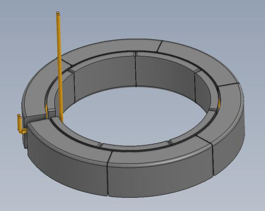
In many energy transmission systems, it is necessary to transmit significantly more power to the secondary side than is possible with the aforementioned system of standard pot cores. In addition, it is often necessary to integrate the coil system - consisting of transmitting and receiving coils - into a customer-specific device. One example of such a system is the rotating energy transmission system, which can be used in motors, signaling devices or sensors. Here, the secondary side is integrated into a component that performs a continuous rotary movement (rotor). The fixed outer coil part (stator) couples electrical energy into the rotor. Such a system is suitable for the contactless transmission of energy and data. The transmission system does not contain any mechanical contact elements such as sliding contacts. Without mechanical contacts, there is no abrasion and the service life and reliability of the device are significantly increased.
- Picture 8 - Rotating energy transmission system, stator

- Picture 9 - Rotating energy transmission system, rotor

Both coils
- Stator/transmitter/primary coil
- Rotor/receiver/secondary coil
are also designed as ferrite core coils in this case. For this special geometry, we use ferrite cores that have been tailored precisely to this application. A special injection molding process enables us to design the ferrite cores in such a way that mechanical, electrical and electromagnetic requirements are met. The result is an effective and space-saving transmission system that can be individually adapted to the ambient conditions.
A closer look at the arrangement of the coil system shows the following views:
- Picture 10 – Coil system of the rotating energy transmission system (rotor and stator)

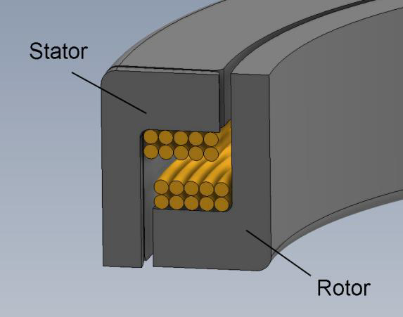
- Figure 11 - Section through rotating energy transfer system

We can also carry out electromagnetic simulations for such systems with special ferrites in order to check the theoretical feasibility of a specification.
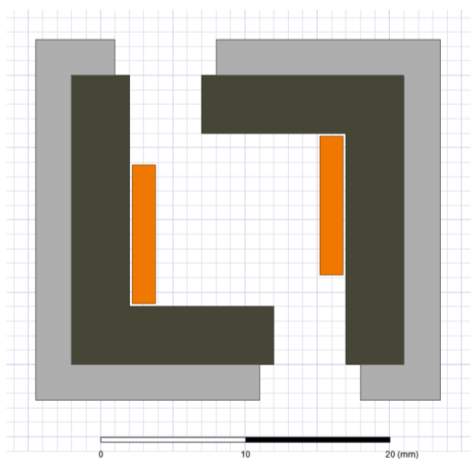
- Picture 12 - Simulation model of a rotating energy transmission system

We have also set up this system and integrated it into a transportable housing to illustrate its function.
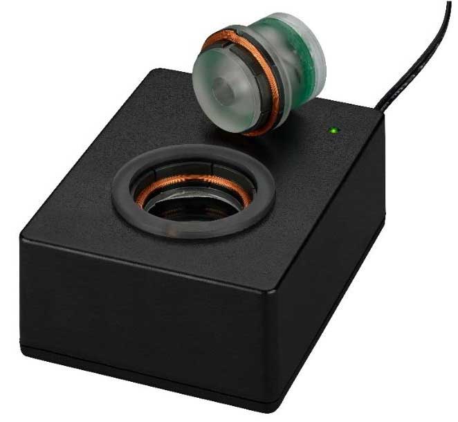
- Picture 13 - Rotating energy transmission system consisting of stator and rotor in housing

This inductive energy transmission system is equipped with a fixed air gap. Depending on the operating frequency, the following power data can be tapped on the secondary side:
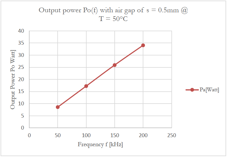
- Picture 14 - Output power of a rotating energy transmission system

The energy transmission systems shown are examples of how such systems can be constructed. Due to the fact that we develop and produce the ferrite cores, they can be created in a wide variety of geometries.
Customer-specific component designs are our specialty! Thanks to our special injection molding process for ferrite cores, we produce custom-fit components for your application - individually according to the defined task and exactly in the specified installation space.
Tell us your requirements – we will develop the right solution for you!
Is this technology of interest to you? Then talk to us about the latest generation of energy transmission systems.