
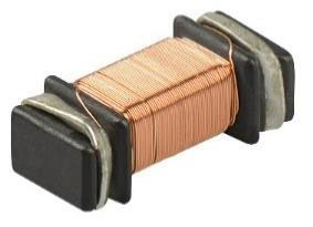
In RFID applications, it is often advantageous that the antenna centre axis is aligned at an angle of 90° to the PCB surface. In this case we speak of Z transponder coils. Based on our proven SMD inductor Ms 42, we have now also designed this component for use as an HF RFID transponder antenna.
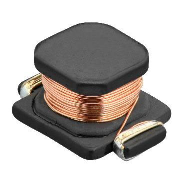
- Picture 1: Ms 42 HF RFID transponder antenna

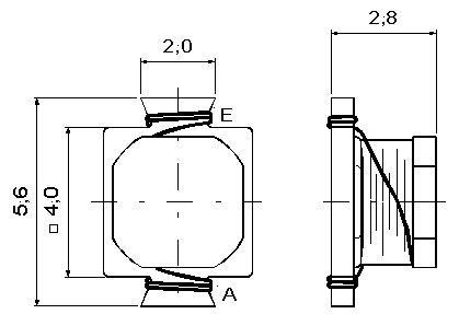
- Picture 2: Ms 42, dimensions (mm)

For this purpose, a core material is used which is particularly suitable for use at an operating frequency of 13.56 MHz. This results in optimal magnetic and electrical properties for operation as a transponder antenna.
Due to the one-piece antenna core, this compact design has excellent mechanical properties, especially high resistance to vibration and mechanical shock. The entire component family meets the requirements of the reliability tests according to AEC-Q200.
With the different input capacities of RFID ICs, transponder antennas with adapted inductance values have to be used so that the overall circuit can be operated at a resonant frequency of 13.56 MHz. The following inductance values are currently available:
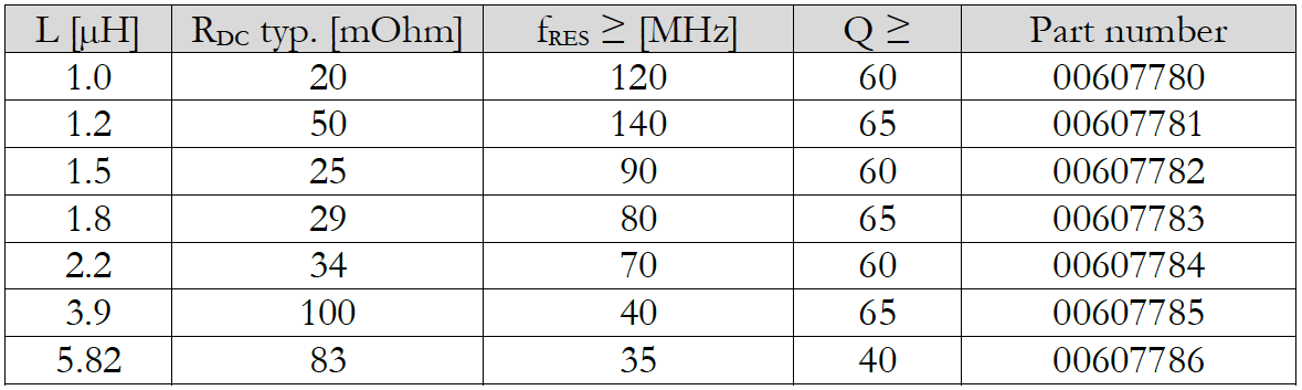
- Table 1: Z transponder antenna Ms 42, current delivery programme

Please contact us if you require different electrical data. We will be happy to support your design idea with custom-fit transponder antennas.
Passive HF/NFC RFID transponders
In the product segment of passive HF/NFC RFID transponders, NEOSID offers a wide range of solutions:
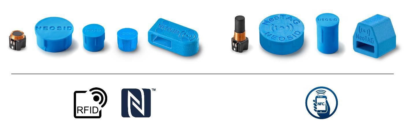
- Picture 3: Overview of the product range of passive HF/NFC RFID transponders

These products are passive stand-alone RFID transponders or RFID chips. For communication between a reader and the transponders, these are placed in the electromagnetic field of the reader antenna. Energy and data transmission are contactless.
Overall, the following equivalent circuit diagram results for a passive RFID transponder:
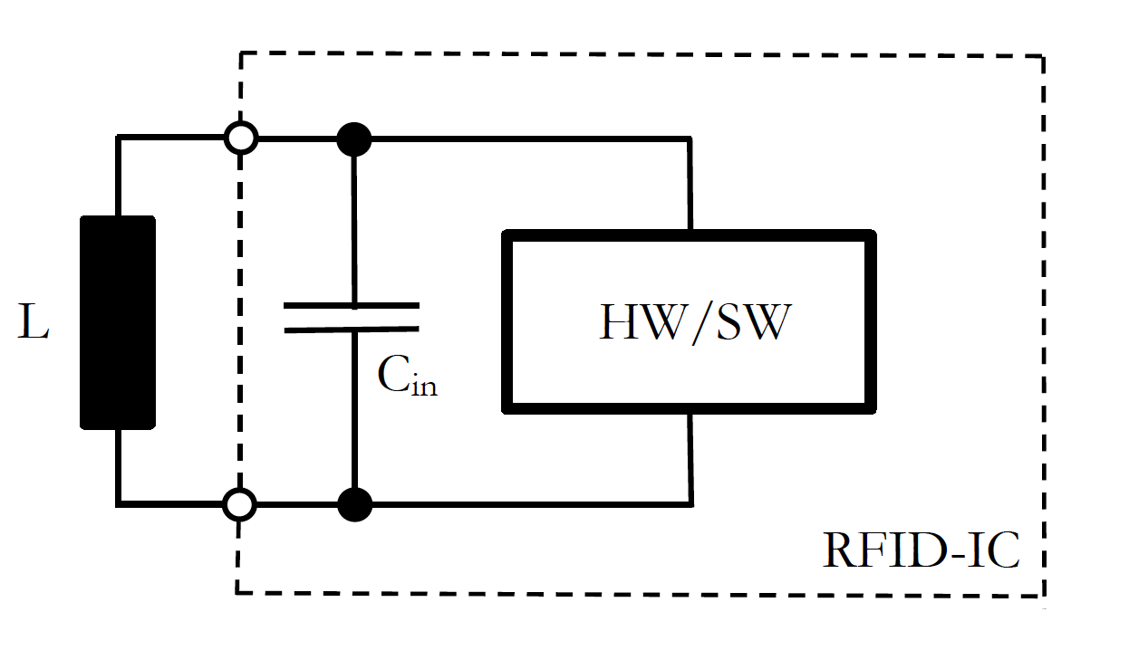
- Picture 4: Passive RFID transponder, equivalent circuit diagram

The oscillating circuit components required for a passive RFID TAG are built up as follows:
The oscillating circuit capacitance Cin is usually realised inside the integrated circuit. There is no discrete capacitor outside the RFID IC. This makes it possible to create transponders with very small mechanical dimensions. The capacitance values are shown in the data sheet as input capacitance Cin. Depending on the RFID IC used, there are different capacitance values between 15 and 100 pF.
The oscillating circuit inductor L works as the antenna of the transponder. In NEOSID transponders, it consists of wound enamelled copper wire. The inductor is designed as an air coil or with a ferrite core - this optimises the magnetic properties of the antenna and, among other things, achieves high reading ranges with a compact design. The beginning and end of the winding are connected to the RFID IC at two contact pads. See pictures above!
The operating voltage generated at the transponder resonant circuit is used for energy and data transmission between the reader and the RFID IC. There are HF RFID ICs from various manufacturers in different designs and with different functionalities.
The following table provides an overview of known HF RFID ICs.
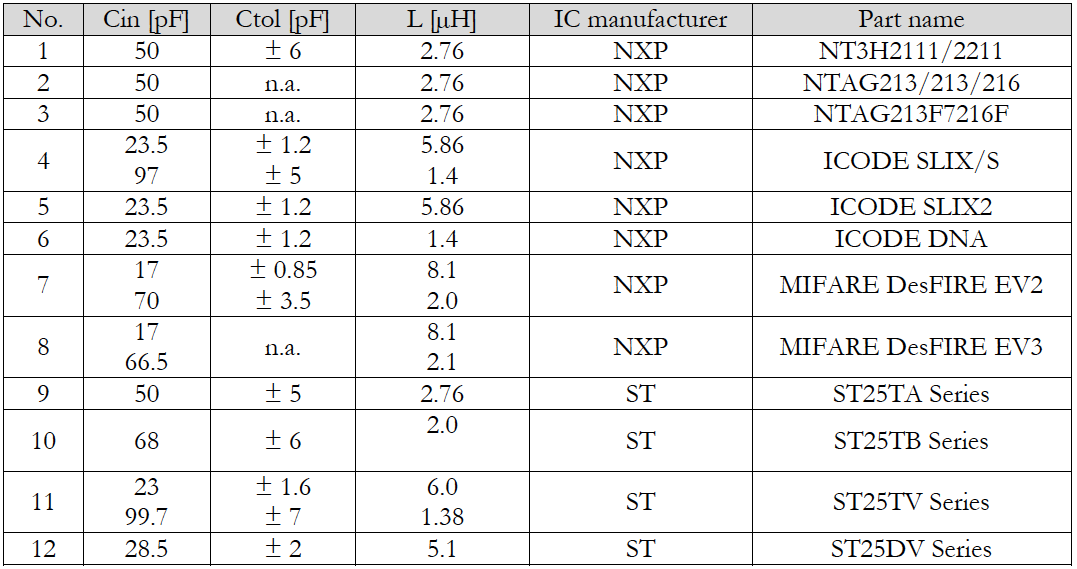
- Table 2: Overview of commercially available HF RFID ICs (not complete)

The table shows2 with which values of Cin the various HF RFID ICs are available and which corresponding antenna inductance must be used to operate the input resonant circuit at a resonance frequency of 13.56 MHz.
Discreetly constructed RFID transponders
Alternatively, a passive RFID transponder can also be constructed with discrete components mounted on a printed circuit board. For this purpose, components in correspondingly suitable designs/housings are used. In such a case, inductive components in axial or radial design can be used for the transponder antenna:

- Picture 5: RFID transponder antenna Ms 42 (radial/Z-design)

- Picture 6: RFID transponder antenna Ms 2046 (axial/ X- and Y-design)

Transponder antennas in axial design
NEOSID components are available in various sizes in axial design. This group of components is also called X, Y transponder coil. The main axis of the antenna is parallel to the PCB surface on which the component is assembled.
- Picture 7: Overview of NEOSID axial transponder antennas

For more details on our axial transponder antennas, please visit our website www.neosid.de under transponder antennas.
Axial transponder antennas are available in different inductance values for each design. Please contact us if you cannot find the design you require or a component with the electrical data you require in the overview.
Customised solutions are our speciality. We are happy to support your design idea with custom-fit transponders, transponder antennas and inductors.
Application examples for discrete RFID transponders
To illustrate possible applications for discrete RFID transponders with axial or radial transponder inductances, we have described two common use cases below.
Application example 1: eol programming
RFID technology is used for other applications besides the design of passive transponders. One example is the use for so-called end-of-line(eol) programming of electronic devices. In this case, electronic devices are manufactured and even packaged in the production process without any final configuration or programming having been carried out. In a final manufacturing step, an RFID interface built into the device is then used to wirelessly import this configuration or even software components into the device. This procedure has the process-technical advantage that the devices can be manufactured independently of the final programming. Special variants of the units can thus be created at a very late stage of production, allowing the production of common parts to be bundled. Finally, device variants are differentiated using different software during eol programming.
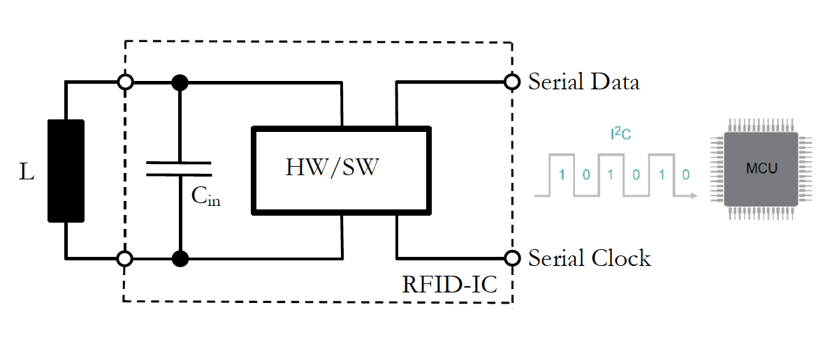
- Picture 8: Passive RFID transponder for eol programming, equivalent circuit diagram

Application example 2: Energy harvesting
In energy harvesting using RFID technology, small amounts of energy are generated and made available to electronic consumers. The electromagnetic field of a reader antenna acts as the energy source. If the passive RFID transponder is placed in the magnetic field, the electronic circuit in the transponder generates an electrical voltage from it, which is made available to consumers on the transponder side. This enables battery- and mains-independent operation of electronic circuits. Applications for such devices are, for example, medical implants with very low power consumption that are to remain in the body for a longer period of time or permanently.
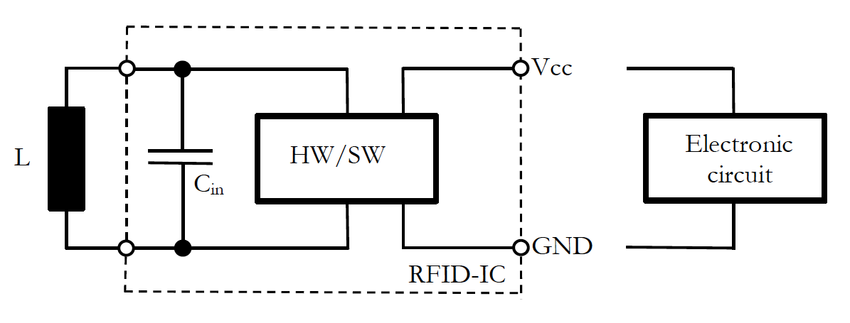
- Picture 9: Passive RFID transponder for energy harvesting, equivalent circuit diagram

Tell us your requirements - we will develop the right solution for you!
Have we aroused your interest? Then contact us about the latest generation of HF/NFC transponder antennas in axial or radial design.