Our product range of NeoTAG® HF RFID transponders/ RFID chips is constantly being expanded and new transponder versions are regularly added. In connection with the use of our transponders, we have compiled a large amount of background information on mounting, function, design, operating behaviour, etc. due to the many applications in which the products are used. As a supplement to our Product Information HF RFID Transponder data sheet, this article contains further technical explanations and application-supporting information.
Our various HF-RFID transponders are used in two different orientations:
1. Rotationally symmetric transponder antenna orientation
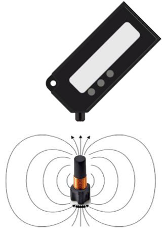
In this orientation, the transponders are inserted vertically into an object to be tagged. To read the transponder, the reader antenna is usually brought to the front of the inserted transponder antenna.
Rotationally symmetrical transponder versions:
- NeoTAG® Plug G/MG3326
- NeoTAG® Plug FG/MFG4335
- NeoTAG® Plug FG/MFG8336
- NeoTAG® Plug FG4670
- NeoTAG® Inlay F/MF2659
- NeoTAG® Inlay F/MF2626

- Picture 6: Rotationally symmetrical HF RFID transponders

- Picture 7: Optimum reading transponder on
- front side
2. 90° orientation of the transponder antenna
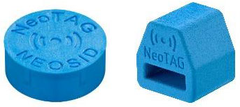
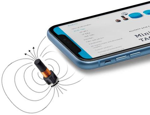
Especially when using mobile devices (smartphones, tablets, ...), it makes sense to offer a larger transponder antenna area. As a rule, the device's internal reader antennas are designed for operation with a credit card. Transponder antennas that are too small thus produce very poor antenna coupling factors. As a solution, we have developed transponders with a 90° rotated antenna orientation for having good NFC reading capability with mobile devices. With these TAGs, the transponder inlays are inserted horizontally into the object to be marked.
Rotationally symmetrical transponder versions:
- NeoTAG Plug FG/MFG10340
- NeoTAG Flag FG7678
- NeoTAG Plug FG4670

- Picture 8: HF RFID transponders with 90° antenna alignment

- Picture 9: NFC reading process with smartphone
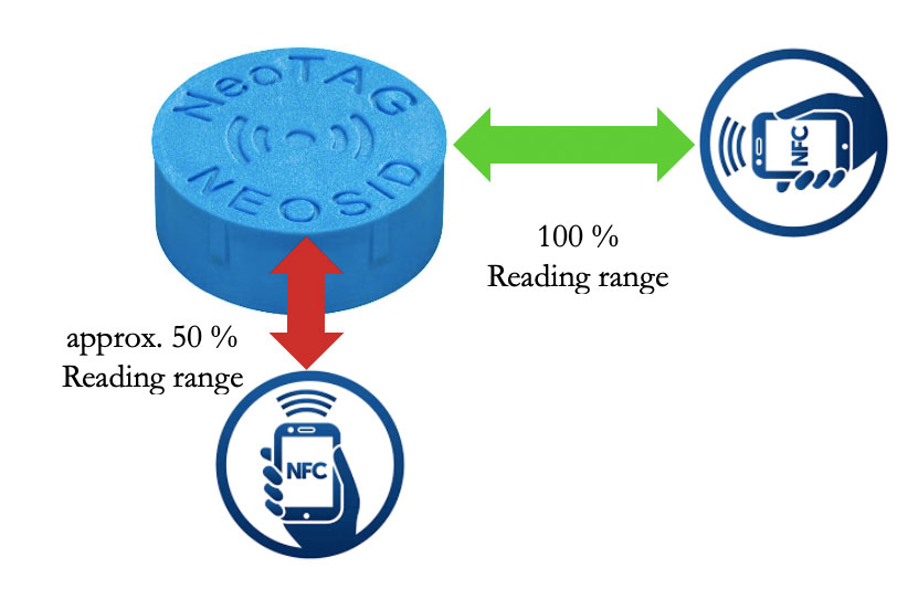
This changed antenna alignment produces different reading ranges depending on the approach direction of the reading antenna to the transponder. These transponders therefore do not have a rotationally symmetrical transponder antenna and require an adapted alignment.

- Picture 10: Reading range with different approach directions on NeoTAG® Plug FG/MFG10340
The internal transponder antenna is placed in the housing with 90° antenna alignment in parallel to the radio logo depicted on the top of the housing.
Tell us your requirements - we will develop the right solution for you.
Have we aroused your interest? Then contact us about RFID transponders for different frequency ranges. Customised solutions are our speciality. We will be happy to support you with our know-how to realise your product development.


